Last Updated on September 21, 2022

by Jon Sunde, Trystar
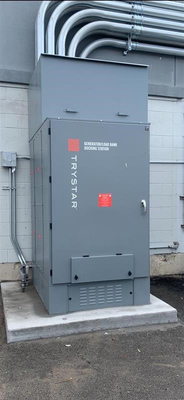
If you’ve ever connected a portable generator to a docking station you have seen this warning label. It’s mandated by the 2020 NEC which says in 702.7(C) “Power Inlet. Where a power inlet (for example, a Trystar docking station) is used for temporary connection to a portable generator, a warning sign shall be placed near the inlet to indicate the type of derived system that the system is capable of based on the wiring of the transfer equipment. The sign shall display one of the following warnings:”
The generator connection must match the signage, but what does it mean and how can you tell which option you have? The difference between a separately derived system vs. a non-separately derived system depends on whether the generator is bonded to the frame or has an unbonded floating neutral.
WARNING:
FOR CONNECTION OF A SEPARATELY DERIVED
(BONDED NEUTRAL) SYSTEM ONLY
OR
WARNING:
FOR CONNECTION OF A NONSEPARATELY DERIVED
(FLOATING NEUTRAL) SYSTEM ONLY
BONDED NEUTRAL VS. FLOATING NEUTRAL
The term “bonded neutral” means that the neutral wire is connected to the generator’s frame. Safety standards state that the neutral must be grounded at the “first means of disconnect” or the nearest possible point. They also require the neutral to be grounded only once, meaning it needs to be transferred from the original source, or your panel, to the generator’s neutral terminal.
This safety code ensures electricity will flow properly through the neutral conductors to one bonded location. It eliminates unpredictable stray voltages since there is only one ground option. This type of bonding causes the generator to behave as a stand-alone unit.
When a generator has a floating neutral, the neutral wire is not connected to the generator’s frame or the ground. Since it has no ground connection on its own, you must connect the neutral to your existing panel for safety. Both slots on the generator are considered live or hot receptacles.
A floating neutral can protect short circuits between hot and neutral wires since it comes in contact with the generator frame and hot leg simultaneously. If there is a short circuit, the currents will have no return path to flow through since the neutral is not bonded to the frame. Instead, the short circuit current will flow through the generator’s metal frame into the ground, providing safety.
HOW DO YOU TELL?
The NEC has addressed this in 445.11 “Marking shall be provided by the manufacturer to indicate whether or not the generator neutral is bonded to its frame. Where the bonding is modified in the field, additional marking shall be required to indicate whether the neutral is bonded to the frame”
SEPARATELY DERIVED SYSTEMS VS. NON-SEPARATELY DERIVED SYSTEMS
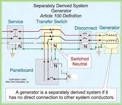
A separately derived system generator’s power is obtained from a source of energy or equipment other than a service. It has no direct connection to circuit conductors other than those established by bonding and ground connections. The grounded neutral conductor is connected via the transfer switch. A separately serviced system works with a bonded neutral generator since safety standards require a single grounding option.
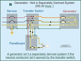
A non-separately derived system uses a switch that only connects the load to the generator’s neutral. It does not transfer the grounded neutral conductor, so it works with a floating neutral that stays connected to the original panel to maintain grounding.
WHICH ONE SHOULD YOU USE?
It all depends on how you are going to hook up your generator.
The service going into the building will have the ungrounded (HOT) conductors and a Grounded (Neutral) conductor. When you terminate your Grounded conductor to its termination you will then install a main bonding jumper from the Grounded termination and then to the can/cabinet, the main bonding jumper.
You will also take your Grounding electrode conductor to the neutral termination, not to the can/cabinet. When you leave your service with a branch circuit or feeder, you will need to install an equipment grounding conductor (EGC) with it.
One of your goals as you are installing or designing an installation is to NOT ever have current on your equipment grounding conductor. If there is a ground fault on a feeder or branch circuit, the fault current will be carried on the EGC back to the service, then onto the main bonding jumper to the grounded conductor going back to the utilities. This is the job of the EGC.
When it comes to adding back-up power to a system, you need to keep a few things in mind. First, make sure when you run your back-up power, it’s not putting power on the utilities providing power for normal use. This will possibly cause a death, but also is illegal in many states.
To do this, you need a switching mechanism to disconnect the ungrounded conductors from the service and connect to the back-up. This is the job of a transfer switch and might include the ability to switch the grounded conductor also.

Whether you need a separately derived system or non-separately derived system is determined by what type of back-up you have. If the generator has its Grounded conductor bonded to the frame you will need to use a transfer switch that will disconnect the grounded conductor from each supply.
If you don’t do this and leave the neutral connected, you will establish a parallel path with your grounded conductor and your EGC. You would then not only be not keeping up with your goals, but you would be violating the NEC rules. Nobody wants to be a violator!
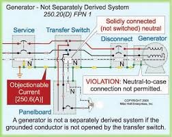
What if the generator is not going to be bonded to the frame? In this case, you will not be switching the grounded conductor at the transfer switch. The reason is you will be using the main bonding jumper at the service to get any fault current back to the gen set to complete the circuit. Either way you choose depends mostly on how the generator will be bonded.
Docking stations can be hooked up by either option. If you are using a trapped key interlock, in most cases, you will be using a non-separately derived system. Please see the attached images provided by Mike Holt.
DEFINING THE TERMS
Bonding Conductor or jumper: A reliable conductor to ensure the required electrical conductivity between metal parts required to be electrically connected.
Bonding Jumper, Main: The connection between the grounded circuit conductor and the equipment grounding conductor, or the supply-side bonding jumper, or both, at the service.
Bonding jumper, supply side: A conductor installed on the supply side of a service or within a service equipment enclosure(s), or for a separately derived system, that ensures the required electrical conductivity between metal parts required to be electrically connected.
Bonding jumper, system: The connection between the grounded circuit conductor and the supply-side bounding jumper, or the equipment grounding conductor, or both, at a separately derived system.
Ground: The earth.
Ground Fault Current Path: An electrically conductive path from the point of a ground fault on a wiring system through normally non-current-carrying conductors, grounded conductors, equipment, or the earth to the electrical supply source.
Grounding Conductor, Equipment (EGC): A conductive path(s) that is part of an effective ground-fault current path and connects normally non-current-carrying metal parts of equipment together and to the system grounded conductor or to the grounding electrode conductor, or both.
Grounding Electrode: A conducting object through which a direct connection to earth is established. Examples: Water Pipe, Metal in-ground support structure, ground rod, etc. found in 250.52(A)
Separately Derived System: An electrical source, other than a service, having no direct connection(s) to circuit conductors of any other electrical source other than those established by grounding and bonding connections.
Service: The conductors and equipment connecting the serving utility to the wiring system of the premises served.
Service Equipment: The necessary equipment, consisting of a circuit breaker(s) or switch(es) and fuse(s) and their accessories, connected to the serving utility and intended to constitute the main control and disconnect of the serving utility.
Three Pole Transfer Switches: Has the means to switch 3 items. See the end note.
Four Pole Transfer Switches: Has the means to switch 4 items. See the end note.
Power Inlet: Comparable to a Trystar docking station
End Note: Four pole vs Three pole is not great terminology because if one is talking about putting in a single phase 120/240-volt separately derived system, they would use a Three Pole Transfer switch. A Four Pole Switching device would give them a separately derived system for a 120/208-volt three phase separately derived system.
LEARN MORE
At Trystar, our team believes in serving each client on a one-by-one basis, providing quality products and stellar service. When you have questions or concerns, we will provide expert and customized advice, making sure we find the perfect solutions for your unique needs. Contact us online today to learn more about our products and services.

We Are Here
To Help
Our team is here to support you and solve your power challenges. Connect with our responsive experts today to learn about our customized power solutions and products.